Spatial Filters Clean Spherical Wavefront Distortion
Guide
Technical Note
Spatial Filters and How to Use Them
The wavefront of a laser beam can be distorted as it goes through an optical system.
Fine dust particles can create disturbing diffraction patterns.
Spacial filters provide a method to remove many of these disturbances, leaving a clean spherical wavefront.
Focusing plane waves with an ideal lens concentrates light at a small spot. In the case of a typical laser beam, where the beam diameter is less than the diameter of the lens, the intensity distribution at the focus spot will have the same gaussian distribution that the incoming laser beam had. If the planar wavefront is disturbed, the intensity distribution at the focus spot will not be the same as the incoming beam anymore.
Instead, the disturbances will alter the intensity distribution such that it has additional spots and rings separate from the central spot. By placing a pinhole at the central spot, the extra spots and rings can be blocked, allowing only the undisturbed wavefront to continue.
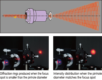
To use a spatial filter, you need to match the hole size to the size of focus point (focus spot) of the objective lens. A hole diameter much larger than the focus spot diameter may not block all of the distortion and noise.
On the other hand, a hole diameter much smaller than the focus spot diameter may produce diffraction rings of concentric circles around a dispersed beam and reduce the total amount of light passed by an unacceptable amount.

A spatial filter consists of a microscope objective lens and a pinhole.
The objective lens is fitted with a linear motion stage for changing the distance to the pinhole and a two-axis pinhole holder that positions the pinhole in a plane perpendicular to the optical axis.
To align the spatial filter holder, refer to the chapter on interferometers.
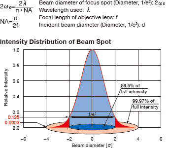
To use a spatial filter, the pinhole diameter needs to match the focus spot diameter.
Calculate the focus spot diameter from the diameter of incident beam and the focal length of the objective lens.
Since the beam spot diameter (2ωο) is defined to be where the intensity falls to 1/e²=0.135 times the peak value, about 15% of incident light intensity will be lost if the pinhole is the same diameter.
Moreover, diffraction rings will be generated when the laser beam irradiates the edge of the pinhole. For this reason, select a pinhole twice as large as the spot diameter (1/e²)
If the pinhole is twice the diameter of the spot, the loss of incident light intensity will be 0.03%, and there will be no need to worry about laser light irradiating on the edge of the pinhole.
Pinhole diameter A=4ωο

Case (A)
He-Ne laser
Objective lens
05-LHP-111
OBL-20
Beam diameter(1/e²)
focal length
0.59mm
9mm
⇒
Pinhole of choice is PA-25 (25µm)
Appropriate product :
SFB-16RO-OBL20-25
Case (B)
He-Ne laser
Objective lens
05-LHP-171
OBL-10
Beam diameter(1/e²)
focal length
1.02mm
16.56mm
⇒
Pinhole of choice is PA-25 (25µm)
Appropriate product :
SFB-16RO-OBL10-25
| Laser Incident Beam Diameter d [mm] |
Objective Lens Focal Length f [mm] |
Calculation Results A [µm] |
Pinhole Diameter (selected) [µm] |
|
|---|---|---|---|---|
| Case (A) | 0.6 | 9.00 | 24.2 | 25 |
| Case (B) | 1.0 | 16.56 | 26.7 | 25 |
Wavelength used 632.8nm
The above calculation results are for when the distance between the laser and the objective lens is short. The longer the distance between the laser and the objective lens, the larger the incident beam diameter becomes due to divergence of the laser beam.
The focus spot diameter decreases in inverse proportion to the increase in the incident beam diameter.
Thus a pinhole of smaller size needs to be selected.
Incident beam diameter can be calculated with the formula shown on the right.
d = dh+α×L
Laser output beam diameter (Diameter, 1/e²): dh
Laser beam divergence (full angle) : α
Distance from laser to objective lens : L

